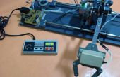
Paso 6: El maestro completo control de código
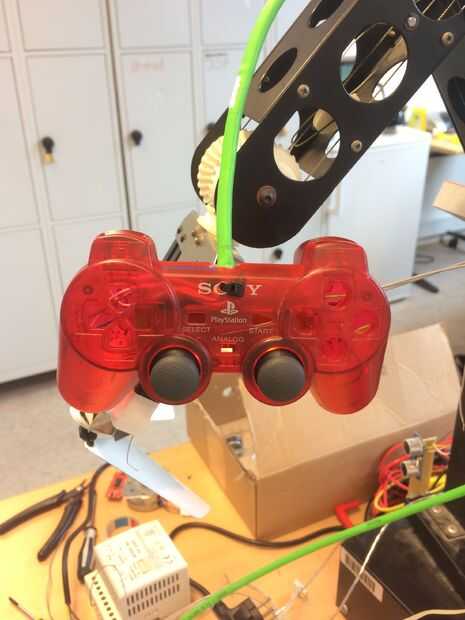
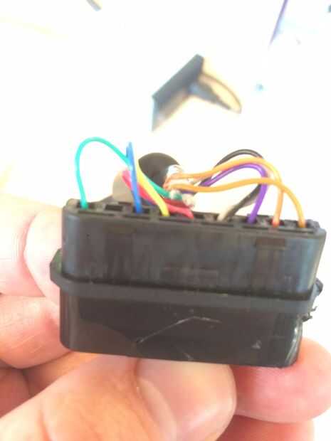
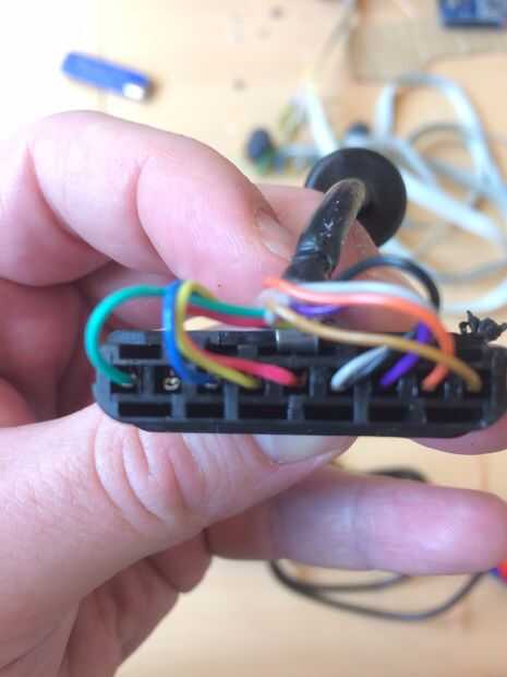
Código completo para brazo robótico que se incluyen a continuación.
Tuvimos algunos problemas con el código que hemos usado, pero puesto que también tuvimos algunos problemas con el voltaje, como se explica en el paso 5, tuvimos un tiempo difícil clasificar a través la mayor parte de todo. Cabe señalar que esta sección del código no contiene el código para el sensor.
<pre><pre>#ifndef _stepLib_h_<br>#define _stepLib_h_ #include "Arduino.h" // define our stepper class class stepMotor { public: stepMotor(byte stepPin, byte dirPin); // our stepper object with variables stepPin and dirPin void step(unsigned int stepFreq); // our stepping function which takes as an input our stepping frequency private: unsigned long _time; // current time unsigned long _lastStepTime; // time at which we last stepped unsigned long _stepPeriod; // time between a half period - this is the same as our delay(X) of part 1 byte _stepPin; byte _dirPin; boolean _stepCycle; // defines if we are on the HIGH or LOW side of our step cycle }; #endif #include "Arduino.h" #include "stepLib.h" // used for declaring our motor and initializing it stepMotor::stepMotor(byte stepPin, byte dirPin) { _stepPin = stepPin; _dirPin = dirPin; // define our digital pins as output pinMode(_stepPin, OUTPUT); pinMode(_dirPin, OUTPUT); // initialize our digital pins to LOW digitalWrite(_stepPin, LOW); digitalWrite(_dirPin, LOW); _stepCycle = false; // this keeps track of which end of the step cycle we are on: high or low } // function responsible for driving our digital pins high/low at the proper frequency // input is the stepping frequency void stepMotor::step(unsigned int stepFreq) { _time = micros(); // get the current time _stepPeriod = 1000000 / stepFreq; // get our step period (in micro-seconds) from the user given step frequency; we lose a bit of accuracy here since we've defined _stepPeriod as an unsigned long instead of a float, but that's ok... // if the proper amount of time has passed, let's go ahead and proceed to the next half of our step cycle if (_time >= _lastStepTime + _stepPeriod) { digitalWrite(_stepPin, _stepCycle == true); // a compact way of writing either HIGH/LOW to our step pin based on where we are on our step cycle _stepCycle = !_stepCycle; // this simply flips our Boolean _lastStepTime = _time; // update the time we last stepped } } #include "stepLib.h" // define a constant value named stepPin and assign the value 8 to it - this value will not change during our code // this assumes digital pin 8 of your Arduino is attached to the step input of your driver #define stepPin 9 // define a constant value named dirPin and assign the value 8 to it - this value will not change during our code // this assumes digital pin 9 of your Arduino is attached to the step input of your driver #define dirPin 8 // instantiate a new object in our stepMotor library named slider // we are essentially declaring that we want to add a stepper motor named slider that has our defined stepPin and dirPin stepMotor slider(stepPin, dirPin); // setup() loop, the Arduino only runs through this once void setup() { } // loop() loop, the Arduino continuously cycles through this as fast as it can void loop() { slider.step(50); // step our motor at a given frequency (Hz) } #include "stepLib.h" // define our step pins # define sliderStep 9 # define panStep 11 # define tiltStep 7 // define our direction pins # define sliderDir 8 # define panDir 10 # define tiltDir 6 // instantiate a new object in our stepMotor library named slider // we are essentially declaring that we want to add a stepper motor named slider that has our defined stepPin and dirPin stepMotor slider(sliderStep, sliderDir); stepMotor pan(panStep, panDir); stepMotor tilt(tiltStep, tiltDir); // setup() loop, the Arduino only runs through this once void setup() { } // loop() loop, the Arduino continuously cycles through this as fast as it can void loop() { slider.step(50); // step our motor at a given frequency (Hz) pan.step(10); // step our motor at a given frequency (Hz) tilt.step(100); // step our motor at a given frequency (Hz) } #ifndef _stepLib_h_ #define _stepLib_h_ #include "Arduino.h" // define our stepper class class stepMotor { public: stepMotor(byte stepPin, byte dirPin); // our stepper object with variables stepPin and dirPin void step(unsigned int stepFreq); // our stepping function which takes as an input our stepping frequency void setDir(boolean dir); // function that allows us to set our direction of rotation private: unsigned long _time; // current time unsigned long _lastStepTime; // time at which we last stepped unsigned long _stepPeriod; // time between a half period - this is the same as our delay(X) of part 1 byte _stepPin; byte _dirPin; boolean _stepCycle; // defines if we are on the HIGH or LOW side of our step cycle }; #endif #include "Arduino.h" #include "stepLib.h" // used for declaring our motor and initializing it stepMotor::stepMotor(byte stepPin, byte dirPin) { _stepPin = stepPin; _dirPin = dirPin; // define our digital pins as output pinMode(_stepPin, OUTPUT); pinMode(_dirPin, OUTPUT); // initialize our digital pins to LOW digitalWrite(_stepPin, LOW); digitalWrite(_dirPin, LOW); _stepCycle = false; // this keeps track of which end of the step cycle we are on: high or low } // function responsible for driving our digital pins high/low at the proper frequency // input is the stepping frequency void stepMotor::step(unsigned int stepFreq) { _time = micros(); // get the current time _stepPeriod = 1000000 / stepFreq; // get our step period (in micro-seconds) from the user given step frequency; we lose a bit of accuracy here since we've defined _stepPeriod as an unsigned long instead of a float, but that's ok... // if the proper amount of time has passed, let's go ahead and proceed to the next half of our step cycle if (_time >= _lastStepTime + _stepPeriod) { digitalWrite(_stepPin, _stepCycle == true); // a compact way of writing either HIGH/LOW to our step pin based on where we are on our step cycle _stepCycle = !_stepCycle; // this simply flips our Boolean _lastStepTime = _time; // update the time we last stepped } } // given a boolean user input, set our direction of travel to that input void stepMotor::setDir(boolean dir) { digitalWrite(_dirPin, dir); } #include "stepLib.h" // define our step pins # define sliderStep 9 # define panStep 11 # define tiltStep 7 // define our direction pins # define sliderDir 8 # define panDir 10 # define tiltDir 6 // define the pins on which we've put our N.O. buttons #define button1 2 #define button2 3 // our motor step frequencies int sliderFreq = 300; int panFreq = 10; int tiltFreq = 100; // instantiate a new object in our stepMotor library named slider // we are essentially declaring that we want to add a stepper motor named slider that has our defined stepPin and dirPin stepMotor slider(sliderStep, sliderDir); stepMotor pan(panStep, panDir); stepMotor tilt(tiltStep, tiltDir); // setup() loop, the Arduino only runs through this once void setup() { // define our button pins as input pullup type - see http://arduino.cc/en/Tutorial/DigitalPins#.Uyphr4WN7q4 pinMode(button1, INPUT_PULLUP); pinMode(button2, INPUT_PULLUP); } // loop() loop, the Arduino continuously cycles through this as fast as it can void loop() { if (digitalRead(button1) == LOW && digitalRead(button2) == HIGH) { // if button1 is pressed and button2 is not pressed slider.setDir(true); pan.setDir(true); tilt.setDir(true); } else if (digitalRead(button1) == HIGH && digitalRead(button2) == LOW) { // if btton1 is not pressed and button2 is pressed slider.setDir(false); pan.setDir(false); tilt.setDir(false); } if (digitalRead(button1) == LOW || digitalRead(button2) == LOW) { // if either button is pressed slider.step(sliderFreq); // step our motor at a given frequency (Hz) pan.step(panFreq); // step our motor at a given frequency (Hz) tilt.step(tiltFreq); // step our motor at a given frequency (Hz) } if (digitalRead(button1) == LOW && digitalRead(button2) == LOW) { // if both buttons are pressed together sliderFreq += 10; panFreq += 10; tiltFreq += 10; delay(10); // delay just a short while otherwise the double button presses causes our frequency to increase too quickly (we need to allow for the user to release the buttons) } } #include "stepLib.h" // define our step pins # define sliderStep 9 # define panStep 11 # define tiltStep 7 // define our direction pins # define sliderDir 8 # define panDir 10 # define tiltDir 6 // define the pins on which we've put our N.O. buttons #define button1 2 #define button2 3 // define our joystick pins; NOTE we are using analog pins, not digital #define LRjoystickPin 27 // left-right joystick #define UDjoystickPin 28 // up-down joystick // our motor step frequencies int sliderFreq = 50; int panFreq = 300; int tiltFreq = 100; // other variables byte deadband = 50; // size of deadband, from joystick neutral position, in which we assume we are reading 0 unsigned int LRjoyValue = 0; unsigned int UDjoyValue = 0; // instantiate a new object in our stepMotor library named slider // we are essentially declaring that we want to add a stepper motor named slider that has our defined stepPin and dirPin stepMotor slider(sliderStep, sliderDir); stepMotor pan(panStep, panDir); stepMotor tilt(tiltStep, tiltDir); // setup() loop, the Arduino only runs through this once void setup() { // define our button pins as input pullup type - see http://arduino.cc/en/Tutorial/DigitalPins#.Uyphr4WN7q4 pinMode(button1, INPUT_PULLUP); pinMode(button2, INPUT_PULLUP); pinMode(LRjoystickPin, INPUT); pinMode(UDjoystickPin, INPUT); } // loop() loop, the Arduino continuously cycles through this as fast as it can void loop() { // read our joystick values and store them LRjoyValue = analogRead(LRjoystickPin); // acts just like digitalRead, but for analog pins UDjoyValue = analogRead(UDjoystickPin); // acts just like digitalRead, but for analog pins // control our pan with the LR joystick if (LRjoyValue > 512+ deadband) { // joystick is outside of deadband, move right pan.setDir(true); pan.step(panFreq); } else if (LRjoyValue < 512- deadband) { // joystick is outside of deadband, move left pan.setDir(false); pan.step(panFreq); } // control our tilt with the UD joystick if (UDjoyValue > 512 + deadband) { // joystick is outside of deadband, move up tilt.setDir(true); tilt.step(panFreq); } else if (UDjoyValue < 512 - deadband) { // joystick is outside of deadband, move down tilt.setDir(false); tilt.step(panFreq); } // control our slider stepper with the two buttons, just like we did previously if (digitalRead(button1) == LOW && digitalRead(button2) == HIGH) { // if button1 is pressed and button2 is not pressed slider.setDir(true); } else if (digitalRead(button1) == HIGH && digitalRead(button2) == LOW) { // if btton1 is not pressed and button2 is pressed slider.setDir(false); } if (digitalRead(button1) == LOW || digitalRead(button2) == LOW) { // if either button is pressed slider.step(sliderFreq); // step our motor at a given frequency (Hz) } }
