Paso 6: Incrustado Aquila acción
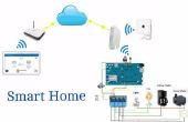
Teniendo todo esto implementado, el código recibido podría simplemente copiar forman el Monitor Serial y pegar como una nueva matriz en el código. Luego, agregar las funciones de la acción de Aquila para llamar matriz de ese (o eso) y tener un mando mejor a través de la plataforma de Aquila (la ventaja de esto es que usted no necesita comprar más botones y que podrás automatizar como mencionaré ahora).
Veo esto como una "sencilla" aplicación para el Altair, imagino que configurarlo para que en la hora N televisor encender y comenzar a grabar su programa favorito.
Ahora, vamos a añadir unas líneas más para aplicar la plataforma de Aquila. Estoy incluyendo una matriz con un montón de números; Estos son los que el control remoto que envía a la TV he usado (que de hecho extrae directamente el Serial Monitor). Tendrás que cambiar esos números para los devuelve el Monitor Serial
Aunque dejaron allí así que podía ver una estructura de matriz.
//Because the timing is very important, we won’t be using digitalRead //for it’s very slow compared with what we’ll be using. //Check the reference link after the code; back on the tutorial. //This (PIND) thing means that form pin 0 to 7 will be READ ONLY #define IRpin_PIN PIND #include <Wire.h> #include <Mesh.h> #include <AquilaProtocol.h></p><p>#define MASK 2 //This will be taken as a binary number (00000010) #define Boton 33 //Built-in Altair Button (It has inverted logif! LOW = Pressed, HIGH = NOT pressed) #define Boton2 10 //Extern button, normal logic! HIGH = Pressed, LOW = Not pressed! #define IR 9 //The longest pulse that will be read is going to be 65ms (when the code applies, it’ll be a microseconds function //So it will NOT be taken as 65000ms (being this 65 seconds); in fact 65 ms is A LOT in this environment. #define MAXPULSE 65000 //Nuestra resolución de tiempo, entre más grande es el valor mejor, //Our time resolution, the bigger the value the better, for it’s more precise //but it takes longer to process it //And we would be losing the precision we won not using digitalRead #define RESOLUTION 20 //El pulso que se recibirá será en pares, 100 pares en éste ámbito es muchísimo //The received pulse will be in pairs, 100 pairs is actually a LOT. uint16_t pulses[100][2]; // Remember that a “value” consist in an ON and OFF from the LED, so in the matrix is stored in pairs. uint8_t currentpulse = 0; // It’ll be used to know how many pairs from ON and OFF have being received. bool full = false;</p><p>uint16_t turnON [120][2]={{46264,1100},{540,1160},{480,1960},{540,1080},{520,1120},{520,1120},{520,1100},{540,1080},{560,1060},{1420,1040},{600,1800},{720,920},{20324,980},{640,980},{660,1780},{740,880},{760,860},{760,880},{760,880},{760,880},{760,860},{1600,900},{760,1700},{760,880},{20384,940},{700,920},{700,1740},{760,880},{760,860},{780,860},{760,880},{760,900},{720,900},{1600,880},{740,1740},{760,860}}; //This is an example of how a code for turning ON a TV looks like, It may be different to yours, so you’ll have to modify the matrix in the next functions (also this one) :)</p><p> uint16_t vUP[120][2]={0}; uint16_t vDWN[120][2]={0}; uint16_t cUP[120][2]={0}; uint16_t cDWN[120][2]={0}; uint16_t inp[120][2]={0}; </p><p>bool encender (uint8_t param, bool gotParam) { Enviar (turnON); delay(500); }</p><p>bool volumenUP (uint8_t param, bool gotParam) { Enviar(vUP); delay(500); }</p><p>bool volumenDWN (uint8_t param, bool gotParam) { Enviar(vDWN); delay(500); }</p><p>bool canalUP (uint8_t param, bool gotParam) { Enviar(cUP); delay(500); }</p><p>bool canalDWN (uint8_t param, bool gotParam) { Enviar(cDWN); delay(500); }</p><p>bool input (uint8_t param, bool gotParam) { Enviar(inp); delay(500); } void setup(void) { Serial.begin(9600); Mesh.begin(); Aquila.begin(); Aquila.setClass("mx.makerlab.test"); Aquila.setName("Control"); Aquila.addAction("Turn On", encender); Aquila.addAction("Volumen +", volumenUP); Aquila.addAction("Volumen -", volumenDWN); Aquila.addAction("Chanel +", canalUP); Aquila.addAction("Chanel -", canalDWN); Aquila.addAction("Input", input); Mesh.announce(HUB); Serial.begin(9600); pinMode(Boton, INPUT); pinMode(Boton2, INPUT); // pinMode(Boton2, INPUT_PULLUP); pinMode(IR, OUTPUT); pinMode(15, OUTPUT); pinMode(14, OUTPUT);</p><p>// 7 6 5 4 3 2 1 0 //TCCR2A - [COM2A1, COM2A0, COM2B1, COM2B0, reserved, reserved, WGM21, WGM20] // 7 6 5 4 3 2 1 0 //TCCR2B - [FOC2A, FOC2B, reserved, reserved, WGM22, CS22, CS21, CS20]</p><p> TCCR2A = _BV(COM2A0) | _BV(COM2B1) | _BV(WGM21) | _BV(WGM20); // A ‘or’ is applies to all of them and it looks like this -> TCCR2A = 0110 0011 (99) TCCR2B = _BV(WGM22) | _BV(CS21); // A ‘or’ is applies and it looks like this -> TCCR2B= 0000 1010 = 10 OCR2A = 25; //Inner time gets to 25 (splitted between the frequency of the micro controller (16MHz) times 2 (because the split will only show the half of the wave, we want to know the duration of a complete cycle. TCCR2A ^= _BV(COM2A1); // Prepares the IR LED</p><p> Serial.println("Ready to decode IR!"); //After this message we’ll know that it has just finished the SETUP part and stats reading pulses. }</p><p>void IRcarrier (unsigned int matrix) { if (matrix != 0) { TCCR2A ^= _BV(COM2A1); //Changes the 8’th bit. Turns the LED ON. delayMicroseconds(matrix); //Waits matrix-microseconds with the LED turned ON. TCCR2A ^= _BV(COM2A1); //Turns the LED off. } }</p><p>void Enviar(uint16_t pulse[120][2]) { digitalWrite(15, LOW); for (int i = 0; i < 120; i++) { if (pulse[i][0] == 0) //If a matrix slot is empty, it leaves the loop. { break; } delayMicroseconds(pulse[i][0]); //Waits n microseconds wi the IR LED off. IRcarrier(pulse[i][1]); //Enters the función sending the delay that takes the ON from the IR } digitalWrite(15, HIGH); }</p><p>//The only thing this función does is printing everything received after the pulse is over. void printpulses() { Serial.println("\n\r\n\rReceived: \n\rOFF\t|\tON"); Serial.print("{"); for (uint8_t i = 0; i < currentpulse; i++) { Serial.print("{"); Serial.print(pulses[i][0], DEC); //DEC <- En caso de que no esté en decimales, esto lo obliga a pasarlo a decimales. Serial.print(","); Serial.print(pulses[i][1], DEC); Serial.print("}"); } Serial.print("};\n"); full = true; } void loop(void) {</p><p>Mesh.loop(); Aquila.loop(); </p><p> digitalWrite(15, HIGH); //Built-in LEDs, inverted logic. digitalWrite(14, HIGH); //Both begin off.</p><p> if (digitalRead(Boton2) == HIGH || (currentpulse != 0)) { if (digitalRead(Boton2) == HIGH) { Serial.println("Leyendo!"); digitalWrite(14, LOW); //GREEN LED ON! full = false; } uint16_t highpulse, lowpulse; // The pulse will be temporary stored on this variables. highpulse = lowpulse = 0; //This process will be splitter in to steps, when the LED is ON; HighPulse and when it’s off; LowPulse. //All this ‘while’ function is for when the pulse is on High (the LED ON) // --- Complex Explanation --- // //We will apply what is on the pin 0-7 a “mask” and we take whatever is on the position 00000100 // If we order the pins this way -> 76543210 we an see in a clearer way that the 00000100 is on the antepenultimate position, same as (xxxxx2xx) //The '&' operator generates a truth table between 00000100 and what is connected to the pins (the micro controller will ignore whatever is not on the pin 2, basically). //So, if there’s anything connected to the PIN 2, it will work. while (IRpin_PIN & (1 << MASK) && full == false) { highpulse++; delayMicroseconds(RESOLUTION); // If the pulse is to long, the scanning ceases. // Writes down everything received and resets counters. if ((highpulse >= MAXPULSE) && (currentpulse != 0)) { printpulses(); currentpulse=0; return; } } // if it never got to the ‘if loop’, then it stores the new high pulse to the matrix. pulses[currentpulse][0] = highpulse; //--------------------------------------------- // The process repeats for the second part of the pulse (remember that it consists on a HIGH and a LOW together) // Is the same as on the other WHILE, only with another notation, where _BV is BITVALUE. Check the assistance links. // And this one will count every time the receiver receives nothing. while (! ( IRpin_PIN & _BV(MASK) ) && full == false) { lowpulse++; delayMicroseconds(RESOLUTION); // If the pulse is too long, the scanning ceases. // Writes down everything received and resets counters. if ((lowpulse >= MAXPULSE) && (currentpulse != 0)) { printpulses(); currentpulse=0; return; } } pulses[currentpulse][1] = lowpulse * RESOLUTION; // A ON-OFF pulse has been read // the whole process will be repeated until some command exceeds the length of a ON or a OFF (and enters to the ‘if loop’). currentpulse++; }</p><p>if (digitalRead(Boton) == LOW && full == true) { Enviar(pulses); delay(500); } digitalWrite(14,HIGH); }</p>
