Paso 6: Conectar Arduino Uno para PC y abra el dibujo.
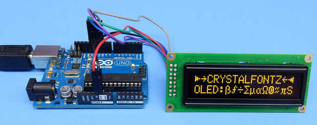
Luego basta con conectar el Arduino al ordenador y abrir el dibujo CFAL1602C_SPI_Arduino.ino. Carga y usted será recompensado con bondad OLED.
//===========================================================================// // Code written for Arduino Uno // // CRYSTALFONTZ CFAL1602C-B CHARACTER OLED IN SPI MODE // // ref: https://www.crystalfontz.com/product/cfal1602c-16x2-character-oled // // 2015 - 10 - 22 Brent A. Crosby //=========================================================================== //This is free and unencumbered software released into the public domain. // //Anyone is free to copy, modify, publish, use, compile, sell, or //distribute this software, either in source code form or as a compiled //binary, for any purpose, commercial or non-commercial, and by any //means. // //In jurisdictions that recognize copyright laws, the author or authors //of this software dedicate any and all copyright interest in the //software to the public domain. We make this dedication for the benefit //of the public at large and to the detriment of our heirs and //successors. We intend this dedication to be an overt act of //relinquishment in perpetuity of all present and future rights to this //software under copyright law. // //THE SOFTWARE IS PROVIDED "AS IS", WITHOUT WARRANTY OF ANY KIND, //EXPRESS OR IMPLIED, INCLUDING BUT NOT LIMITED TO THE WARRANTIES OF //MERCHANTABILITY, FITNESS FOR A PARTICULAR PURPOSE AND NONINFRINGEMENT. //IN NO EVENT SHALL THE AUTHORS BE LIABLE FOR ANY CLAIM, DAMAGES OR //OTHER LIABILITY, WHETHER IN AN ACTION OF CONTRACT, TORT OR OTHERWISE, //ARISING FROM, OUT OF OR IN CONNECTION WITH THE SOFTWARE OR THE USE OR //OTHER DEALINGS IN THE SOFTWARE. // //For more information, please refer to //=========================================================================== //Software SPI (10-bit transfers, difficult to do using the hardware SPI) #define SPIPORT (PORTB) #define SPITOGGLE (PINB) // PB5 (0x20) is SCK (output) green OLED pin 12 #define SPI_SCK_PIN (13) #define SCK_MASK (0x20) #define CLR_SCK (PORTB &= ~(SCK_MASK)) #define SET_SCK (PORTB |= (SCK_MASK)) // PB4 (0x10) is MISO (input) blue OLED pin 13 //(reference only, it is an input) #define SPI_MISO_PIN (12) #define MISO_MASK (0x10) #define CLR_MISO (PORTB &= ~(MISO_MASK)) #define SET_MISO (PORTB |= (MISO_MASK)) // PB3 (0x08) is MOSI (output) violet OLED pin 14 #define SPI_MOSI_PIN (11) #define MOSI_MASK (0x08) #define CLR_MOSI (PORTB &= ~(MOSI_MASK)) #define SET_MOSI (PORTB |= (MOSI_MASK)) // DB2 (0x04) is SS (output) gray OLED pin 16 #define SPI_SS_PIN (10) #define SS_MASK (0x04) #define CLR_SS (PORTB &= ~(SS_MASK)) #define SET_SS (PORTB |= (SS_MASK))#define DATA (1) #define COMMAND (0) //=========================================================================== void write_to_OLED_SPI(uint8_t destination,uint8_t data) { //Bits sent in this order: // data(1)/command(0) flag // read(1)/write(0) flag // data.7 (msb) // data.6 // data.5 // data.4 // data.3 // data.2 // data.1 // data.0 (lsb) #if(1) //Pretty fast software SPI 10-bit transfer code //Several ideas taken from the fastest non-assembly implementation at: //http://nerdralph.blogspot.com/2015/03/fastest-avr-software-spi-in-west.html // // The SS pin is low for ~3.8uS, the clock frequency is ~ 2.6MHz // 47x faster than above //Pre-calculate the value that will drive clk and data low in one cycle. //(Note that this is not interrupt safe if an ISR is writing to the same port) register uint8_t force_clk_and_data_low; //Select the chip CLR_SS; //Pre-calculate the value that will drive clk and data low in one //operation. force_clk_and_data_low = (SPIPORT & ~(MOSI_MASK | SCK_MASK) ); //Set clock and data low SPIPORT = force_clk_and_data_low; //Set the data(1)/command(0) flag if(DATA==destination) { SPITOGGLE = MOSI_MASK; } //Use a toggle to bring the clock up SPITOGGLE = SCK_MASK; //Set clock and data low SPIPORT = force_clk_and_data_low; //MOSI is already 0, for read(1)/write(0) flag as write //Use a toggle to bring the clock up SPITOGGLE = SCK_MASK; //Now clock the 8 bits of data out SPIPORT = force_clk_and_data_low; if(data & 0x80) SPITOGGLE = MOSI_MASK; SPITOGGLE = SCK_MASK; SPIPORT = force_clk_and_data_low; if(data & 0x40) SPITOGGLE = MOSI_MASK; SPITOGGLE = SCK_MASK; SPIPORT = force_clk_and_data_low; if(data & 0x20) SPITOGGLE = MOSI_MASK; SPITOGGLE = SCK_MASK; SPIPORT = force_clk_and_data_low; if(data & 0x10) SPITOGGLE = MOSI_MASK; SPITOGGLE = SCK_MASK; SPIPORT = force_clk_and_data_low; if(data & 0x08) SPITOGGLE = MOSI_MASK; SPITOGGLE = SCK_MASK; SPIPORT = force_clk_and_data_low; if(data & 0x04) SPITOGGLE = MOSI_MASK; SPITOGGLE = SCK_MASK; SPIPORT = force_clk_and_data_low; if(data & 0x02) SPITOGGLE = MOSI_MASK; SPITOGGLE = SCK_MASK; SPIPORT = force_clk_and_data_low; if(data & 0x01) SPITOGGLE = MOSI_MASK; SPITOGGLE = SCK_MASK; //Release the chip SET_SS; #else //Straight-forward software SPI 10-bit transfer code, perhaps //easier to understand, possibly more portable. Certainly slower. // // The SS pin is low for ~180uS, the clock frequency is ~57KHz // 47x slower than above //Select the chip, starting a 10-bit SPI transfer digitalWrite(SPI_SS_PIN, LOW); //(bit 0) Set the data(1)/command(0) flag if(DATA==destination) digitalWrite(SPI_MOSI_PIN, HIGH); else digitalWrite(SPI_MOSI_PIN, LOW); //Clock it in. digitalWrite(SPI_SCK_PIN, LOW); digitalWrite(SPI_SCK_PIN, HIGH); //(bit 1) Clear the read(1)/write(0) flag to write, clock it in. digitalWrite(SPI_MOSI_PIN, LOW); //Clock it in. digitalWrite(SPI_SCK_PIN, LOW); digitalWrite(SPI_SCK_PIN, HIGH); //(bits 2-9) Push each of the 8 data bits out. for(uint8_t mask=0x80;mask;mask>>=1) { //Set the MOSI pin high or low depending on if our mask //corresponds to a 1 or 0 in the data. if(mask&data) { digitalWrite(SPI_MOSI_PIN, HIGH); } else { digitalWrite(SPI_MOSI_PIN, LOW); } //Clock it in. digitalWrite(SPI_SCK_PIN, LOW); digitalWrite(SPI_SCK_PIN, HIGH); } //Release the chip, ending the 10-bit SPI transfer digitalWrite(SPI_SS_PIN, HIGH); #endif } //=========================================================================== void position_cursor(uint8_t column, uint8_t line) { //Set CGRAM Address, RS=0,R/W=0 // 7654 3210 // 1AAA AAAA // 0x00 to 0x27 => Line 1 // 0x40 to 0x67 => Line 2 write_to_OLED_SPI(COMMAND,0x80 | (line?0x40:0x00) | (column & 0x3F)); } //=========================================================================== // According to the WS0010 data sheet, only the clear display time has // an appreciable execution time of 6mS. All others are listed at 0. void clear_display(void) { //Display Clear RS=0,R/W=0 // 7654 3210 // 0000 0001 write_to_OLED_SPI(COMMAND,0x01); _delay_ms(6); } //=========================================================================== void initialize_display() { //Refer to WS0010 data sheet, page 21 // https://www.crystalfontz.com/products/document/3176/WS0010.pdf //The display controller requests: // "Wait for power stabilization 500ms: _delay_ms(500); //Function set, RS=0,R/W=0 // 7654 3210 // 0011 NFFT // N = lines: N=1 is 2 lines // F = Font: 0 = 5x8, 1 = 5x10 // FT = Font Table: // FT=00 is English/Japanese ~"standard" for character LCDs // FT=01 is Western European I fractions, circle-c some arrows // FT=10 is English/Russian // FT=11 is Western European II my favorite, arrows, Greek letters write_to_OLED_SPI(COMMAND,0x3B); //Graphic vs character mode setting, RS=0,R/W=0 // 7654 3210 // 0001 GP11 // G = Mode: 1=graphic, 0=character // C = Power: 1=0n, 0=off write_to_OLED_SPI(COMMAND,0x17); //Display On/Off Control RS=0,R/W=0 // 7654 3210 // 0000 1DCB // D = Display On // C = Cursor On // B = Cursor Blink write_to_OLED_SPI(COMMAND,0x0E); //Display Clear RS=0,R/W=0 // 7654 3210 // 0000 0001 clear_display(); //Display home write_to_OLED_SPI(COMMAND,0x02); //Entry Mode Set RS=0,R/W=0 // 7654 3210 // 0000 01IS // I = Increment/or decrement // S = Shift(scroll) data on line write_to_OLED_SPI(COMMAND,0x06); //Display Clear RS=0,R/W=0 // 7654 3210 // 0000 0001 clear_display(); } //=========================================================================== void setup() { //General setup, port directions. // PB5 (0x20) is SCK (output) green OLED pin 12 pinMode(SPI_SCK_PIN, OUTPUT); // PB4 (0x10) is MISO (input) blue OLED pin 13 //(reference only, it is an input) pinMode(SPI_MISO_PIN, INPUT); // PB3 (0x08) is MOSI (output) violet OLED pin 14 pinMode(SPI_MOSI_PIN, OUTPUT); // DB2 (0x04) is SS (output) gray OLED pin 16 pinMode(SPI_SS_PIN, OUTPUT); } //=========================================================================== void loop() { //Simple demo loop, shows a screen of text, including high order characters //( see page 10 of https://www.crystalfontz.com/controllers/WinstarDisplay/WS0010/378 ) // //Then there is a screen with solid characters on the left, and 50% //checkerboard characters on the right. // Initialize the display initialize_display(); //Display text screen // 0123456789012345 char line1[17]=">}CRYSTALFONTZ{<"; line1[ 0]=0xF6; // right triange; line1[ 1]=0xC7; // right triange; line1[14]=0xC8; // left triange; line1[15]=0xF7; // left triange; // 0123456789012345 char line2[17]="OLED:aaaaaaaaaaS"; line2[ 5]=0xE0; //beta line2[ 6]=0xA8; //function line2[ 7]=0xB8; //divide line2[ 8]=0xDA; //sigma line2[ 9]=0xEA; //mu (micro) line2[10]=0xDF; //alpha line2[11]=0xDE; //omega line2[12]=0xCF; //circle C line2[13]=0x1A; //about equal line2[14]=0xED; //pi // write to the first line position_cursor(0,0); for(int col=0;col<16;col++) { write_to_OLED_SPI(DATA,line1[col]); } // write to the second line position_cursor(0,1); for(int col=0;col<16;col++) { write_to_OLED_SPI(DATA,line2[col]); } //Show the text message for a bit _delay_ms(1000); //Use the custom characters (CGRAM) to make the //left half solid, the right half checkerboard //Set CGRAM [0], to solid write_to_OLED_SPI(COMMAND,0x40 | (0 <<3)); for(int i=1;i<=8;i++) write_to_OLED_SPI(DATA,0xFF); //Set CGRAM [1], checkerboard write_to_OLED_SPI(COMMAND,0x40 | (1 <<3)); for(int i=1;i<=4;i++) { write_to_OLED_SPI(DATA,0xAA); write_to_OLED_SPI(DATA,0x55); } // write to the first line position_cursor(0,0); for(int col=0;col<8;col++) { write_to_OLED_SPI(DATA,0); // CGRAM[0] } for(int col=8;col<16;col++) { write_to_OLED_SPI(DATA,1); // CGRAM[1] } // write to the second line position_cursor(0,1); for(int col=0;col<8;col++) { write_to_OLED_SPI(DATA,0); // CGRAM[0] } for(int col=8;col<16;col++) { write_to_OLED_SPI(DATA,1); // CGRAM[1] } //Show the pattern for a bit _delay_ms(1000); } //===========================================================================


